
- Spi serial flash programmer schematic diagram how to#
- Spi serial flash programmer schematic diagram pdf#
- Spi serial flash programmer schematic diagram update#
- Spi serial flash programmer schematic diagram driver#
- Spi serial flash programmer schematic diagram manual#
Spi serial flash programmer schematic diagram how to#
This is also a follow-on to my other two data-logging Instructables (an and a ) that explains how to download the data from the logger flash memory using age-old TTY command line applications found in Linux.MotivationWhenever I'm building an Atmel ATMega or Arduino project and I need to record data, I almost always reach for a single rather than an SD flash subsystem. This Instructable will show you how to add 1MB of discrete external flash memory to your microcontroller project with what I believe to be the least amount of effort possible. Since VC2008 you have a class for the serial port, i think it is some kind of stream object in the end.ĭesigning with discrete flash is 1/10th the cost, uses a much smaller form factor, and requires significantly less specialized hardware than using SD flash cards. So you need a small application to do this. Also on the PC side you have a hex file, and somehow you need to convert it into a serial data stream.
Spi serial flash programmer schematic diagram manual#
It can program a lot of chips.What you need to do is to implement the specification from the 8051 controller manual into a flow char and then into a C source code.You have the RS232 signals on one side, and the SPI interface on the other side, and the firmware on the microcontroller inbetween.To buy a FLASH writer for the 8051 chip would be the least effort but if you want, program the firmware for a FLASH writer yourself.It is not difficult just for one chip, but in order to support an array of controllers, it would take some effort.It is certainly doable. Have you compared the programming spec with one of the AVR chips?The only problem might be to support it in the software. If you still want to go further and really use a USB to RS232 chip, the programming process will be very slow.With a microcontroller, given you know the protocol, you can program any other microcontroller. But these are used by serial programmer softwares. It is as slow as 1mSec to toggle control lines. Maybe I did not give a good answer on the first try, but since the intention to help is there, maybe we are moving towards a solution.edit: One reason why you need a microcontroller is the USB framework. I clicked one link on the page I linked, and it describes programming a blank chip with an FTDI cableIsn't that what you want to do? From the webpage, it seems to be possible.

Maybe not but I think I do understand it somehow.
Spi serial flash programmer schematic diagram driver#
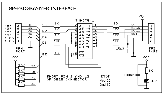
It seems that it might be possible with a different driver since the cable has 4 data lines which is what SPI needs.If it is the simple matter of converting the data sent out over the FTDI cable into SPI with clock signals, I can do this easily with a microcontroller.īuilding anything more complicated than that might be beyond my abilities. It has an SPI interface described here: Is it possible to program the chip with only an FTDI cable?Someone recommended I look into avrdude but I have not found support. For the fuses setting consult the datasheet of the respective u-controller.I would like to program an AT89LP6440. Also make sure do not program the RSTDISBL fuse in the AVR series devices, unless it is necessary otherwise further serial programming is disable, to restore the serial programming a high voltage parallel programmer is required. The main view of the program is shown in figure 3. Figure 2: Stand-alone SPI Programming interface Software The SpiPgm37.zip file contains the main program and the io port driver. The 74HCT04 is used to generate the clock signal for the u-controller when programming the device in stand-alone mode.įigure 1: Circuit Diagram of the SPI Flash Programmer. It is necessary to use the HCT type IC in order to make sure the programmer should also work with the 3V type parallel port. The 74HCT367 IC buffer the parallel port signals. – Page program: 0.8ms.įigure 1 shows the circuit diagram of the SPI Flash programmer hardware interface, the power to the interface is provided either by a 9V dc adapter or a 9V battery. 3V, 1Mb Page Erasable with Byte Alterability. Figure 1 shows the circuit diagram of the SPI Flash programmer., to restore the serial programming a. The interface sinks current from the PC serial port, so it doesn't need any external power. You can connect any of the following adapter card to the 10 pin connector. Base board SI-Prog base: connect it to the PC DB9 serial port. MDA2061/MDA2062 are similar to NVM3060, but they also need a 20V at pin 3 and 1KHz clock at pin 13. X2444 use the same socket as 93Cxx (not rotated pinout).
Spi serial flash programmer schematic diagram pdf#
Complete schematics are available in Acrobat PDF file format:: current board in production NB: AT17Cxx eeprom use the same socket as DS1621 (U10 in the PDF schematics.
Spi serial flash programmer schematic diagram update#
Last update $Date: 5 23:21:01 $ All schematics in this page are copyrighted © by Claudio Lanconelli, you need my permission before to publish them in your site, magazine or other media. Spi Serial Flash Programmer Schematic Diagram 9,8/10 3627reviews


 0 kommentar(er)
